Showing posts with label gpio. Show all posts

Wednesday, 1 February 2017

First Look at the BBC Micro:bit

This blog was supposed to be about getting my kids to code and explore electronics.  Recently it's focused on other things so it was great recently when my eldest daughter brought her BBC micro:bit home from school.

Read all about the initiative here but effectively it's a free mini-computer given out by the British Broadcasting Corporation to all year 7 secondary school children in the UK.  It's a super simple computer that kids can get coding on very easily and is meant to inspire children to get into Technology.

Because there's a very high probability I'd break her Micro:bit I decided to buy my own.  Here's the box it came in.  Nice and bright and inviting:


Inside the box you get what's shown on the image below.  From left to right you can see:

  • The Micro:bit
  • Batteries, battery box and connector lead
  • Documentation

(This is actually the micro:bit "go".  You can buy just the board on it's own as well).


Looking close up at one side you can see:

  • A micro-USB connector (top middle)
  • A reset button (right of USB)
  • A power connector (right of reset button)
  • Labels pointing to the bluetooth antenna, main processor, accelerometer and compass. 


On the other side you can see:

  • The General Purpose Input Output connector at the bottom.  This has 5 big tracks to connect a crocodile clip or bana plus to plus a load of other pins.
  • Two input buttons
  • A 5x5 LED array


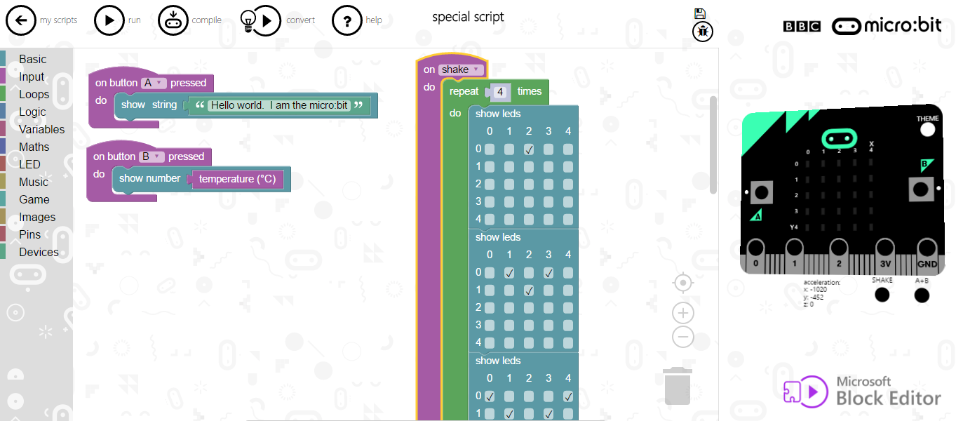
Getting started with coding is soooooooooooo simple.  Just go to the Micro:bit site, select "Let's Coding" and choose a coding method.  We chose the Microsoft Block Editor which is a super simple scratch like interface.

Two minutes later we had the all important "Hello World" completed, could read the temperature off the board and could create a pattern of LEDs.  Here's an example screenshot.  So simple, doesn't really need an explanation.


You can then press "run" to simulate the code on the board on the right hand side of the screen.  When you're happy with it you press "compile" which creates .hex file on your PC.  Then just connect the micro:bit to your PC with a USB cable, transfer the file and watch it run!

Overall a great piece of kit that we'll have a lot of fun playing with.

Saturday, 11 April 2015

Raspberry Pi Powered Ultra Sonic Sensing Minion Fart Gun Triggering Machine

One of the trials of 21st century life is having to trigger your own Despicable Me Minion fart gun.  Hence I thought it would be a good use of time and resources to build an automatic Minion fart gun triggering machine*.

(* I am being sarcastic by the way!  It was just a bit of Geek fun with a Raspberry Pi).

Here it is in action, (I'll then tell you how I built it):


So the idea is that the ultra sonic sensor determines when you're close to it and starts the motor which runs the machine that pulls the trigger and sets off the minion farts.

Part 1 - The Fart Gun Trigger Pulling Machine
Using my old-skool 1980s Technical Lego I built a machine that can pull the trigger on the Minion Fart gun.  Here's some pictures:


So key design features are:
  • A Lego Power Functions motor.
  • Which runs through a "gear box" to step down the speed.
  • Which powers a large Lego sprocket.
  • Which has an "arm" connected off-centre, thus turn rotary motion into reciprocating motion.
  • Which pushes a beam backwards and forwards.
What this does subsequently is easier to see on the image below:


Connected to the beam is a set of  Lego axles which are pushed backwards and forwards.  The very front axle hooks around the Fart Gun trigger to make it go off.  This is adjustable to make sure the trigger is pulled the correct amount.  A few guides with smooth tile pieces make sure everything is aligned and nothing is caught up.  Overall I had to do a lot of strategic strengthening to make sure that when the trigger is pulled the whole contraption doesn't pull itself apart.

Here's a video of it powered with a Lego battery box.


Part 2 - Ultra Sonic Sensor
I've used an HC-SR04 ultra-sonic sensor for a couple of previous Raspberry Pi Scratch projects like a press up counting machine and a simple game.  Previously I've used Scratch but for this project I decided to use Python to understand a little more about how to control the sensor and interpret the results.

I followed this tutorial, it's utterly brilliant.   I won't replicate it here but the highlights are:

  • Principles of potential dividers (required to drop the sensor's 5V output down to 3.3V for the Raspberry Pi).
  • Wiring up the sensor.
  • Python code for setting up and controlling the GPIO.
  • Python code to trigger a measurement (creating a short pulse).
  • Python code to capture the echo response duration.
  • The physics and maths behind interpreting the length of the echo pulse and turning it into a distance measurement.
It's just fascinating how tangible it is to do this through Python on the Raspberry Pi.  The result is the bulk of the code I've pasted in at the bottom of this posting.  You have:
  • Function GetAMeasurement - Which takes a measurement
  • A main loop that continuously gets a measurement and acts upon the result.

Part 3 - Controlling Motors
For this I re-used techniques I first learnt about for my Lego car project.  Read more about it there but it basically uses a motor controller board to take logic output from Raspberry Pi GPIO pins and switch on the Lego motor.  Never connect the output of the Raspberry Pi to a motor as you'll damage the Pi!

Key snippets of Python code are.
1)Constants for the GPIO pin numbers:
MOT1 = 17
MOT2 = 21

2)Defining the pins as GPIO outputs:
GPIO.setup(MOT1,GPIO.OUT)
GPIO.setup(MOT2,GPIO.OUT)

3)Controlling the pins based upon distance measurements:

  if (TheDistance < 100):
    #Switch motor on
    print "Get farting!"
    GPIO.output(MOT1, True)
    GPIO.output(MOT2, False)
  elif (TheDistance < 10):
    #Switch motor off
    GPIO.output(MOT1, False)
    GPIO.output(MOT2, False)
  else:
    #Switch motor off
    GPIO.output(MOT1, False)
    GPIO.output(MOT2, False)

So if the measurement from the sensor is greater than 100cm or less than 10cm, keep the motor turned off.  Otherwise, turn the motor on by setting one of the GPIO pins as high.  I do the < 10cm check for Lego maintenance purposes, (i.e. if it breaks!).  It means that by covering the sensor I can leave the Python script running and be close to the sensor to tinker with stuff without triggering the farts.

Aside - Wiring it Up
One thing I learnt during this project was the different ways to reference the pins on the Raspberry Pi GPIO.  On previous projects I've specified:

GPIO.setmode(GPIO.BOARD)

...which means reference the pins exactly how they're laid out on the GPIO.  e.g. Pin 11 in the code refers to pin 11 on the GPIO.

The code from the ultra sonic sensor tutorial specified:

GPIO.setmode(GPIO.BCM)

...which means reference the pins how the Broadcom chip references them.  This is explained on this Stack Exchange answer.  What I actually did is best explained with a picture.  Here's how I had it wired up:


Here's a picture of it wired up:


When looking at the sensor from behind:
  • The right hand pin is VCC and is wired to +5V on the Pi.
  • The next to right hand pin is Trig and the green jumper wire goes to GPIO23 as shown on the diagram above.
  • The left hand pin is Ground and is wired to Ground on the Pi.
  • The next to left hand pin is Echo and has a 2k ohm resistor coming from it to a spare track on the bread board.  From the same track, the yellow jumper wire goes to GPIO24 on the Pi and the 1k ohm resistor goes to the Ground rail (which is connected to Ground on the Pi). 


All the Code
As ever on the Geek Dad blog, here's all the code:

#Used https://www.modmypi.com/blog/hc-sr04-ultrasonic-range-sensor-on-the-raspberry-pi as a tutorial

#Import statememts
import RPi.GPIO as GPIO
import time
import datetime

#Set GPIO numbering mode
GPIO.setmode(GPIO.BCM)
GPIO.setwarnings(False)

#Constants for the trigger and echo pins
#http://raspberrypi.stackexchange.com/questions/12966/what-is-the-difference-bet
ween-board-and-bcm-for-gpio-pin-numbering
TRIG = 23
ECHO = 24
MOT1 = 17
MOT2 = 21

#Other constants
WaitVar = 1

#Initial message
print 'Distance Measurement In Progress'

#Set up our GPIO inputs and outputs
GPIO.setup(TRIG,GPIO.OUT)
GPIO.setup(ECHO,GPIO.IN)
GPIO.setup(MOT1,GPIO.OUT)
GPIO.setup(MOT2,GPIO.OUT)

#Routine to initialise the sensor
def InitaliseSensor(TrigPin):
  #Initialise the sensor
  GPIO.output(TrigPin, False)
  print "Waiting For Sensor To Settle"
  time.sleep(2)

def GetAMeasurement(TrigPin,EchoPin):
  #Send a pulse that is 10us long
  GPIO.output(TrigPin, True)
  time.sleep(0.00001)
  GPIO.output(TrigPin, False)

  #Keep looping while we wait for a response
  while GPIO.input(EchoPin)==0:
    pulse_start = time.time()  #So when we come out of this loop the start time will be logged

  #Now keep looping while the response comes in (pin is high)
  while GPIO.input(ECHO)==1:
    pulse_end = time.time()    #So when this loop ends the end time will be logged

  #Calculate pulse duration
  pulse_duration = pulse_end - pulse_start

  #Speed = Distance / Time. Hence Distance = Speed * Time.  Speed is speed of sound = 343m/s or 34300cm/2.  Divide resulting answer by 2 as it's a return trip
  distance = pulse_duration * 17150
  distance = round(distance,2)

  #return the distance
  return distance

####Main code body####
#Initialise the sensor
InitaliseSensor(TRIG)

while True:
  #Get the distance
  TheDistance = GetAMeasurement(TRIG,ECHO)

  #Print the result
  print "Distance:",TheDistance,"cm"

  #Wait a bit
  time.sleep(WaitVar)

  #See if someone is close
  if (TheDistance < 100):
    #Switch motor on
    print "Get farting!"
    GPIO.output(MOT1, True)
    GPIO.output(MOT2, False)
  elif (TheDistance < 10):
    #Switch motor off
    GPIO.output(MOT1, False)
    GPIO.output(MOT2, False)
  else:
    #Switch motor off
    GPIO.output(MOT1, False)
    GPIO.output(MOT2, False)

#Clean up the GPIO
GPIO.cleanup()


Sunday, 1 March 2015

Ultrasonic Elephant Cheese-puff Game using Raspberry Pi and Scratch

In two previous posts I've written how my kids and I used an ultra sonic sensor, Raspberry Pi and Scratch to make a press up counter and a cuddly toy theft alarm.  One deficiency in those projects was that the Scratch/GPIO capability could only take an ultra-sonic measurement every one second.  In particular, for the press up counter I had to do the press ups REALLY slowly to get them to count. Too much like hard work!

A bit more investigation on Simple Si's epic Scratch/GPIO site showed that he has created a capability using an "UltraDelay" variable which means you can take a reading every 0.2 seconds.  So this means you can many more measurements and so, racking my brains to think what we could do with this, I had the idea of making the Scratch cat levitate by moving my hand up and down over the ultra sonic sensor.  A extension of this was to create a Scratch game, using the sensor to control a sprite's position.

Here's what we came up with:

  • Have a sprite moving across the screen from right to left at random heights.  When it reaches the left hand side of the screen it returns to the right hand side and re-starts at a new height.
  • Have a sprite that moves up and down the screen based upon the position of your hand over the sensor.  If this sprite touches the right to left sprite then you score points.
  • Have this happening for a fixed period of time and then have the final score read out at the end.

Here's the code for the right to left sprite:

So a very simple block of code:
  • Start when g (for game) is pressed.
  • Set the initial position of the sprite as x=200, y=-100.  This is on the right edge of the screen towards the bottom.
  • Loop 600 times.  
  • For each loop, move the x position of the sprite by -13 steps. 
  • If the sprite gets to an x position of -180 (left hand side of the screen) then move it back to the right hand side of the screen but at a random height that is somewhere between -200 (bottom of screen) and 200 (top).
There was some excellent learning to be had just in this short block of code:
  • x and y coordinates on the screen.
  • Loops, and changing the loop variable to get the game time we needed.
  • Experimenting with the number of steps to move the sprite by for each loop.  The final value of -13 was found to be just the right number to make the game challenging but not too challenging.
  • An if statement and an action taken should the statement be true.

Which leaves the (slightly more complex) code for the second sprite:
Here we:
  • Again start by pressing g.
  • Set the UltraDelay variable to 0.  This means a reading is available every 0.2 seconds.
  • Set a HitCount variable to 0, this was incremented when the sprites touch.
  • Set the sprite to it's initial position.  x = -100 is left of centre meaning there's time to move the sprite into position to hit the right to left sprite.
  • Go into a loop with 600 iterations, the same as for the other sprite.
  • Broadcast for an ultrasonic measurement.
  • Get the response and then set the y position of the sprite to be (value * 10) - 200.  Having -200 meant that when the value is very low (or zero) the sprite moves to the bottom of the screen.  Having * 10 means that 40cm worth of hand movement over the sensor can translate to 400 steps of movement of the sprite.
  • A check to see of the sprite is touching the right-left sprite.  If it is then increment a variable to count the number of touches and play a pop sound.
  • When the main 600 iterations are done, go into a loop that reads out the final score.

So in doing this we learnt:
  • About setting and incrementing variables
  • About maths statements, taking one value and transposing it to another.
  • The simple concept of taking a real world value and turning this into an on-screen analogue.

Which left the important task of choosing the sprite icons.  For this we used:
  • A bowl of cheese puffs for the right to left sprite.
  • An elephant for the up and down sprite.

You ask why?  I say why not!!!

Here's the game in action:


Future improvements:
  • A high score feature.
  • Having only one point scored when the sprites touch (should be able to use a simple boolean for this).


Sunday, 22 February 2015

Ultra Sonic Pinky Pig Anti-Theft Device

Meet Pinky Pig:


Pinky Pig is the most loved soft toy in the Geek household.  He's been owned by my eldest daughter since birth, is a a bit worse for wear these days but is loved all the same.  In fact Pinky Pig rarely leaves the house,such would be the trauma of losing him.

In a search for something new to do with our ultra sonic sensor (see last week's post), we came up with the idea of using the ultra sonic sensor to make a device to detect if Pinky has been stolen.  In simple terms, Pinky's resting place would be on the ultra sonic sensor.  If he was taken then this could be detected and an alarm raised.  

We had a lot of fun (and a lot of learning) coming up with the Scratch code below on one of our Raspberry Pi's.  It was a really good way to focus on the role of a loop and an if statement.


So if the measurement from the sensor is small, all is well and no alarm is raised.  However if the measurement is not small then the (audible) alarm is raised.

We we did learn which was interesting was that Pink Pig (and other cuddly toys) are transparent to ultra sonic sound waves.  Very interesting, this added an extra layer of investigation to this project.  Please comment below if you can tell me why this is the case.  Hence to make the alarm work, Pinky had to be wrapped in an extra layer of paper.  Here's a picture showing this in action.


So last thing, here's a video of it in action (wish the volume on the TV was louder - listen carefully and you can hear the alarm going off).


Monday, 16 February 2015

Raspberry Pi Ultra Sonic Press Up (Push Up) Counting Machine using Scratch

Looking at back at recent posts I've noticed:
  • I've not done any electronics related projects recently.
  • I've not done much programming with my kids recently.
When doing some press ups* recently I lost count and couldn't log them on my Jerks exercise logging system.  Hence this gave me the idea to build a machine to count my press ups.

(*Push ups for you readers in North America)

I saw you can buy one from Amazon and there are some available as smart phone apps but this isn't the Geek Dad way; I wanted to build one with a Raspberry Pi, program it in Scratch and use some electronics.  Ideas:
  • Mount a light dependent resistor - as I go down it blocks out light from the LDR, as I go up it allows light again and counts a press up.
  • Use a camera and a QR code.  As I go down it reads the QR code and counts a press up.
  • Use an ultra sonic sensor to measure distance as I go up and down.
I decided to use an ultra sonic sensor - purely because I'd hadn't used one since a University project about 20 years ago.  Here's the one I bought, an HC-SR04 module which has both a transmitter and a receiver.  They're widely available on the interweb.


To integrate the sensor to my Raspberry Pi I used the utterly amazing, epic and awesome Cymplecy Scratch GPIO system (did I mention that this site is brilliant).  This chap has developed a series of Scratch releases that allow you to integrate with many and various third party boards and bits of electronic kit that you can connect to the GPIO.  There's a specific page on Ultra Sonic module integration; it's available here and the solution only uses one GPIO input/output which is ace.

The resistors shown on the breadboard diagram on Cymplecy's site are essential to stop you blowing up your Raspberry Pi; they create a potential divider to reduce the +5V output from the HC-SR04 to a GPIO friendly 3.3V.  The resistors are:
  • Brown-Black-Red = 1kOhms
  • Red-Red-Red = 2.2kOhms
I won`t do the maths here, but see this site for an explanation of potential dividers.

The system works brilliantly and with this code block you can get Scratch to show the measurement from the ultra sonic sensor and move the Scratch Cat around.


So this worked beautifully, next I needed a robust housing for the press up counting machine to avoid me breaking it.  Enter Lego, the tool of tinkerers everywhere.  Here's a series of before, during and after shots:


So the breadboard is mounted perpendicular in the Lego housing, meaning the sensor points straight up.  Hence as I'm doing press ups I'm moving up and down vertically over the sensor.  The Raspberry Pi sits separate to it.

Here's a quick video:


The basic algorithm for the press up code is as follows:

boolean = false
forever
  Take Measurement
  if Measurement < Low AND boolean = false
    boolean = true
  if Measurement > High and boolean = true
    increment press up count
    boolean = false

So this uses a simple boolean to log when my body is low down (say < 10cm from the sensor).  The spots the bottom part of the press up.  Then when I move up, if my body is high up (say > 30cm) AND I've previously been low down then a press up is counted (and the boolean is reset).

The basic Scratch code is shown on the screen shot below (put your email address in a comment below and I'll send you the file).  This does a good job of counting press ups (although you have to go quite slow as the sampling period is only one second) and getting the Scratch Cat to say them.


What I wanted to do with my daughters is jazz it up a bit.  In preparation for this I recorded a number of different audio messages for Scratch to play out.  I used this site which takes a text string input and provides a downloadable MP3 file.  These files can then be put in the /usr/share/scratch/Media/Sounds directory on your Raspberry Pi.  Armed with this I spent an enjoyable afternoon with my daughters making the press up counter more interesting.

We:
  • Changed the background to make it look better.
  • Added a sound at the start to tell you that "It's press up time!".
  • Added If statements to detect each Press Up (up to 10) and play an audio message with the number ("1" for the first press up, "5" for the fifth etc).
  • Added some motivational (semi-abusive) messages to keep you going.
  • Added a "Well Done" message at the end.

Here's a video of it in action!


Here's a screenshot of the Scratch code (top part). A but hard to see so, again, put your email address in comments below and I'll send you the Scratch file.


...and bottom part:


Sunday, 5 January 2014

An AirPi - Useful in a Powercut

In March 2013 I built a Raspberry Pi AirPi and I've had it up and running ever since.  The system has proved to be very reliable; I reckon it's only stopped working 2 or 3 times since I set it up.  The Python scripts are setup to run when the Pi starts so the AirPi will automatically start up if there's a power cut or glitch.

I do this by putting scripts in the /etc/init.d folder.  Here's an example:

#Used this as a guide http://myraspberrypiexperience.blogspot.co.uk/2012/08/star
t-vnc-automatically.html
#Run this under the Pi username
export USER='pi'
eval cd ~$USER

#Run the Airpi
su $USER -c 'sudo python /home/pi/Meteoros/pdw_upload_v3.py &'

#End stuff
exit 0

We've had some pretty wet and windy weather in the UK over the Christmas period (it's still poor as I write early in the new year) which has resulted in long power cuts all over the country.  We suffered a power cut at my house for 26 hours from roughly 1300 on 23/12/2013 to 1500 on 24/12/2013.  

Here's my AirPi barometric pressure chart for the period:


On the graph you can see the pressure suddenly drop; the weather conditions that coincided with this were high winds and heavy rain.  This caused trees to be blown over which caused a power cut to the place I live in which you can see on the graph as the horizontal line from the 23rd to the 24th.  A power cut means no power to the RasPi and no ADSL router, hence there are no measurements for this period.

The AirPi came in useful as we were due as a family to travel to my in-laws on the 24th for Christmas.  It's a reasonably long drive so we were due to leave at 0830ish on the 24th.  With the power out we decided to stay put as we didn't know what state the house would be in when the power came back on (i.e. freezer defrosted, lights left on).  However by 1200 the power was still off and with a long drive ahead of us we decided to give a key to neighbour, switch off everything we could, chuck out a load of food from the freezer and then crack on with the drive.

In the end the drive went well and we arrived before 1600.  Then, just after 1600 I got a Twitter direct message from my Raspberry Pi, (more on that later), which let me know that it was up and running again.  Shortly after I got a text from my neighbour to tell me that all was well with the house.

The next question was whether the heating would come on properly after the power cut; it would be a bad thing not to have this on during winter.  My AirPi gave me the answer as I could see the temperature in the house going up and down twice a day.  (I could monitor this remotely via Xixely).


It was interesting to look at the temperature profile, (chart for the 25th shown below):

The heating came on in the early hours of the morning and then early in the afternoon which matched the twice a day timer program I had set.  It heated up to roughly the expected temperature  (the thermostat was in another room and set to 19 Celsius).  It was good to see that the room heated up quicker than it cooled down which shows that the insulation must be doing some good.  What was interesting was the the heating was coming on several hours earlier than expected.  What I assumed (and later proved) was that when the power came on at 1600, the clock on the heating controller must have resumed at the time it held when the power went off(1300).  Hence the clock was running roughly 3 hours fast. 

It's also interesting to compare the fairly regular temperature profile while we were away (two peaks a day, a longer one in the afternoon) with one when we were at home the next week:

The "at home" peak is a lot more messy as we control the heating manually, tinker with the main thermostat and TRVs, open doors and windows etc.

I mentioned earlier that the thing that prompted me that the power was back on was a tweet from the Raspberry Pi. I have the Pi GET a temperature measurement from Xively and send it to me as a Twitter direct message (which I can pick up on my Android handset).  The fact that I get one of these every hour just tells me that the Pi is still up and working and it's also good for inter-geek boasting!

I used this utterly excellent document from the Raspberry Pi Foundation to tell me how to tweet from the Pi using Python (see page 115).  The code is below (secret values edited out) but in simple terms, every hour it picks up the latest temperature reading from Xively and posts it as a Twitter direct message.  It uses the twitter Python module.  Here's a screenshot:


#Using Twitter to communicate COSM values
#Example URL is http://api.cosm.com/v2/feeds/XXXXX.csv?datastreams=0
#This returns the last value for datastream 0
import os
from twitter import *
import time
from datetime import datetime
from httplib import HTTP

#The URL we will use
COSMURL = "api.cosm.com"
FullCOSMURL = "http://api.cosm.com/v2/feeds/104017.csv?datastreams=0"
KeyToUse = <Deleted>

#Make a HTTP request to COSM to get a string
def GetCOSM():
  try:
    #Now do the HTTP magic - Connect to the server
    h = HTTP(COSMURL)

    #Do a get
    h.putrequest('GET',FullCOSMURL)

    # setup the API Key
    h.putheader('X-ApiKey',KeyToUse)

    # we're done with the headers....
    h.endheaders()

    #Get the response
    errcode, errmsg, headers = h.getreply()
    response = h.getfile()
    data = response.read()
    h.close()
    print data
    return data
  #Catch an exception
  except Exception, err:
    #Write a log with the error
    print "Got us an exception: " + str(err)

#MAIN BODY OF CODE
#Go in to a loop sending direct messages
while True:
  #Using the @mrjamesbond account to send tweets
  #Went to https://dev.twitter.com/apps/new to set this up
  CONSUMER_KEY = <Deleted>
  CONSUMER_SECRET = <Deleted>

  # get full pathname of .twitterdemo_oauth file in the
  # home directory of the current user
  oauth_filename = os.path.join(os.path.expanduser('~'),'.twitterdemo_oauth')

  # get twitter account login info
  if not os.path.exists(oauth_filename):
    oauth_dance('Raspberry Pi Twitter Demo', CONSUMER_KEY, CONSUMER_SECRET, oauth_filename)
  (oauth_token, oauth_token_secret) = read_token_file(oauth_filename)

  # log in to Twitter
  auth = OAuth(oauth_token, oauth_token_secret, CONSUMER_KEY, CONSUMER_SECRET)
  twitter = Twitter(auth=auth)
  try:
   #Send a direct message
   MessageToSend = "AirPi Temperature Reading " + GetCOSM()
   #print MessageToSend
   twitter.direct_messages.new(user="pauldavidweeks",text=MessageToSend)

   # Tweet a new status update
   #twitter.statuses.update(status=MessageToSend)

   # Display all my tweets
   #for tweet in twitter.statuses.user_timeline():
     #print('Created at',tweet['created_at'])
     #print(tweet['text'])
     #print('-'*80)
  except:
    print "Got a Twitter error"

  time.sleep(3600)